Showing posts with label Tutorial. Show all posts

Tuesday, April 05, 2016

Performant Stylized Shaders in Unity - Shader Basics

This tutorial is for people who wish to know the basics of fast shaders, and are already somewhat familiar with programming and working with 3D content!

A shader is a piece of code that runs on your graphics card, and determines how triangles are drawn on the screen! Typically, a shader is composed of a vertex shader, for placing vertices in their final location the screen, and a pixel shader (generally referred to as a ‘fragment shader’) to choose the exact color on the screen! While shaders can often look very confusing at a first glance, they’re ultimately pretty straightforward, and can be a really fun blend of math and art!

Creating your own shaders, while not particularly necessary with all the premade ones running about, can lend your game a really unique and characteristic look, or enable you to achieve beautiful and mesmerizing effects! In this series, I’ll be focusing on shaders for mobile or high-performance environments, with a generally stylized approach. Complicated lighting equations are great and can look really beautiful, but are often out of reach when targeting mobile devices, or for those without a heavy background in math!

In Unity, there are two types of shaders, vertex/fragment shaders, and surface shaders! Surface shaders are not normal shaders, they’re actually “magic” code! They take what you write, and wrap it in a pile of extra shader code that you never really get to see. It generally works spectacularly well, and ties straight into all of Unity’s internal lighting and rendering systems, but this can leave a lot to be desired in terms of control and optimization! For these tutorials, we’ll stick to the basic vertex/fragment shaders, which are generally /way/ better for fast, un-lit, or stylized graphics!

You can create a simple vertex/fragment shader in Unity by right clicking in your Project window->Create->Shader->Unlit Shader! It gives you most of the basic stuff that you need to survive, but here I’m showing an even more stripped down shader, without any of the Unity metadata attached! This won’t compile by itself, it does need the metadata in order to work, but if you put this in between the CGPROGRAM and ENDCG tags, you should be good to go! (Check here for how the full .shader file should look!)

#pragma vertex   vert
#pragma fragment frag

#include "UnityCG.cginc"

struct appdata {
 float4 vertex :POSITION;
};
struct v2f {
 float4 vertex :SV_POSITION;
};

v2f vert (appdata data) {
 v2f result;
 result.vertex = mul(UNITY_MATRIX_MVP, data.vertex);
 return result;
}

fixed4 frag (v2f data) :SV_Target {
 return fixed4(0.5, 0.8, 0.5, 1);
}


Breaking it down:
#pragma vertex   vert
#pragma fragment frag

The first thing happening here, we tell CG that we have a vertex shader named vert, and a pixel/fragment shader named frag! It then knows to pass data to these functions automatically when rendering the 3D model. The vertex shader will be called once for each vertex on the mesh, and the data for that vertex is passed in. The fragment shader will be called once for each pixel on the triangles that get drawn, and the data passed in will be values interpolated from the 3 vertex shader results that make its triangle!

struct appdata {
 float4 vertex :POSITION;
};
struct v2f {
 float4 vertex :SV_POSITION;
};

One of the great thing about shaders is that they’re super customizable, so we can specify exactly what data we want to work with! All function arguments and return values have ‘semantics’ tags attached to them, indicating what type of data they are. The :POSITION semantic indicates the vertex position from the mesh, just as :TEXCOORD0, :TEXCOORD1, :COLOR0 would indicate indicate texture coordinate data for channels 0 and 1, and color data for the 0 channel. You can find a full list of semantics options here! These structures are then used as arguments and return values for the vertex and fragment shaders!

v2f vert (appdata data) {
 v2f result;
 result.vertex = mul(UNITY_MATRIX_MVP, data.vertex);
 return result;
}

The vertex shader itself! We get an appdata structure with the mesh vertex position in it, and we need to transform it into 2D screen coordinates that can then be easily rendered! Fortunately, this is really easy in Unity. UNITY_MATRIX_MVP is a value defined by Unity that describes the Model->View->Projection transform matrix for the active model and camera. Multiplying a vector by this matrix will transform it from its location in the source model (Model Space), into its position in the 3D world (World Space). From there, it’s then transformed to be in a position relative to the camera view (View Space), as though the camera was the center of the world. Then it’s projected onto the screen itself as a 2D point (Screen Space)!


The MVP matrix is a combination of those three individual transforms, and it can often be useful to do them separately or manually for certain effects! For example, if you want a wind effect that happens based on its location in the world, you would need the world position! You could do something like this instead:

v2f vert (appdata data) {
 v2f result;
 
 float4 worldPos = mul(_Object2World, data.vertex);
 worldPos.x += sin((worldPos.x + worldPos.z) + _Time.z) * 0.2;
 
 result.vertex = mul(UNITY_MATRIX_VP, worldPos);
 return result;
}


Which transforms the vertex into world space with the _Object2World matrix, does a waving sin operation on it, and then transforms it the rest of the way through the View and Projection matrices using UNITY_MATRIX_VP! For a list of more built-in shader variables that you can use (like _Time!) check out this docs page!

fixed4 frag (v2f data) :SV_Target {
 return fixed4(0.5, 0.8, 0.5, 1);
}

And last, there’s the fragment shader! This takes the data from the vertex shader, and decides on a Red, Green, Blue, Alpha color value. Alpha being transparency, but we’ll need to dig through Unity’s metadata for that! In this case, we’re just returning a simple color value, so it’s a solid value throughout! Here, you may notice the return value is a fixed4 rather than a structure, but note that it still uses the :SV_Target semantic for the return type at the end of the function definition! If you’re wondering the difference between float4 and fixed4, it’s basically 128 bits of accuracy vs 32 bits, more on that later, but we only really need to return 32 bits of color data back to the graphics card! 

Again though, we can do cool math with this too! In this case, just attach the x and y axes to the R and G channels of the color!

fixed4 frag (v2f data) :SV_Target {
 return fixed4(
  (data.vertex.x/_ScreenParams.x)*1.5, 
  (data.vertex.y/_ScreenParams.y)*1.5, 
  0.5, 
  1);
}

So that’s the basics of the syntax for creating shaders in Unity! You can do a fair bit with this already, but the real fun bits come in when you tie into Unity’s inspector, using textures for color and data, and a bit of graphics specific math! We’ll get into that next time, but for now, here are the final shader files with their Unity metadata wrapper which were used to create the screenshots you see here!

Sunday, June 23, 2013

Quickly placing random objects in a landscape without overlap

For me, creating procedural content is one of the most awesome things ever! Despite having created it yourself, you're still not quite sure what you'll expect this time. So today I'm going to discuss a problem that I often have: placing objects randomly in a scene, without having them overlap eachother!

It's a small scene, but nothing's overlapping, not even with the path. Looks like the code works to me!

The easiest approach to creating a random landscape is to just launch into a for loop, and just start assigning random coordinate! And that's often pretty great all by itself, but you'll get -tons- of overlap.

Sooo... let's just check if it overlaps with anything, and if it does, assign it a new random position? Great! What if there's no room, or very little room? You could easily spend a lot of loops trying to pick a good spot, or even worse, catch yourself in an infinite loop. It also takes an unpredictable duration, which is generally a bad idea.

The solution I've decided on isn't perfect, but it is a decent approximate, and it's fairly fast. The idea is to create a grid over the area, and use each cell in it to store the distance to the nearest object. If we're using a bounding circle to determine where an object will fit, then these values should instantly tell us whether or not that cell is a valid location!

ASCII Visualizations are the best.

As you can see here, we've got an ASCII gradient, to show distance from a single placed object, with 'x' marking the actual areas the object takes up. The data is actually stored as floats, so it's very simple to tell the actual distance. Here's the code I used to make it:

PlacerRandom random = new PlacerRandom(0);
Placer placer = new Placer(20, 20, random);
placer.PlaceCircle(4, 4, 2);
placer.DebugDistance();

You can find the Placer code at the bottom of this post. From here, it's pretty simple to pick out valid cells, and then choose one of those to spawn your object at. Using the placer's GetCircle method, you can pick out a random location that will fit a given radius.

This scene contains a path, and 4 objects. It looks a bit more confusing.

I also discovered the need to add paths through my world, so I wanted to be able to set lines that would be clear of stuff. Using the closest point on a line algorithm with a distance test, it's not hard to do exactly the same sort of thing with a line. Here's the code I used to create this scene:

PlacerRandom random = new PlacerRandom(0);
Placer placer = new Placer(20, 20, random);
placer.PlaceLine(0, 8, 20, 15, 1f);
   
float x = 0, y = 0;
float radius = 2;
for (int i = 0; i < 4; i++) {
 placer.GetCircle(radius, out x, out y);
 placer.PlaceCircle(x, y, radius);
}
placer.DebugDistance();

The speed for these is pretty excellent on small maps, for a 32x32 grid, getting and placing 100 circles was about 3ms on my machine. Unfortunately, this goes up pretty fast, with a 128x128 grid taking about 33ms for the same thing. Fortunately, it's not likely you'll be doing this sort of thing every frame, but if you're generating tiles as you move, having a hiccup might not be ideal either.

There's plenty of room for optimization, better math, different distance algorithms, silly things, but it's already pretty workable.

Oh, and don't forget, even after you've placed all those objects, that distance information can still be pretty handy! As you can see in my leading image, I've used it to do some fake shadow estimates. With a bit of tweaking, that'll look excellent =D

You can download the code for Placer.cs and PlacerRandom.cs. I haven't really polished them yet, I still consider them a WIP , but it should be pretty easy to use! Also, this code should work right away in Unity.

Sunday, March 25, 2012

Basic XNA Post Shader Tutorial

So here's going to be a really simple, basic introduction to post shaders in XNA! If you aren't familiar with what a post shader is, try thinking of the popular special effects like Bloom, or Motion Blur. These are special effects that get done after the entire screen has been completely drawn! A shader or two is then used to manipulate the resulting image to do something cool.

In this example, I will show you how to do a simple single pass post shader using basic color information. More advanced techniques will use more than just color information, and use multiple layers of post shaders. So for this example, we're just going to invert the colors of the screen!

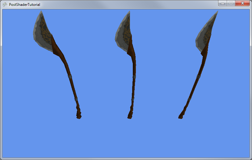
I'm going to start with a basic project that draws a simple model to the screen, you can follow this tutorial here, or just download this project as a starting point. If you just need a 3D model to get you started, you're also welcome to use these: glaive model, glaive texture.


These are the things that we'll need to do to get this post stuff working:

  • Make a post shader
  • Load it
  • Create an off-screen surface to draw to
  • Draw to the off-screen surface
  • Draw the off-screen surface using the post shader
And fortunately, none of these bits are particularly hard. One or two might be a little arcane, but that's what webpage bookmarks and copy/paste are for ;)

We'll start at the top with defining our variables, so first! Define this in your Game1.cs, right below the GraphicsDeviceManager and SpriteBatch.

Effect         postShader;
RenderTarget2D offscreenSurface;

So the Effect will store our post shader, it's essentially the exact same thing as any other shader you might deal with, but the devil is in the details. You'll see exactly what I'm talking about when you get to the .fx file for it! The RenderTarget2D holds our off-screen surface, it's basically a Texture2D that's been specialized for having things rendered to it. You can also use it for things like mirrors or reflections on water, or even TV screens and security cameras!

Next would be initializing them. So in the Game1 LoadContent method, add these lines:

postShader       = Content.Load<Effect>("PostShader");
offscreenSurface = new RenderTarget2D(graphics.GraphicsDevice,
                                      graphics.GraphicsDevice.Viewport.Width,
                                      graphics.GraphicsDevice.Viewport.Height,
                                      false,
                                      graphics.GraphicsDevice.DisplayMode.Format,
                                      DepthFormat.Depth24);

We'll add in the PostShader.fx file shortly, but check out that constructor for RenderTarget2D! You can see there, we're specifying the viewport width and height. This tells it how large the texture we're storing for it will be. The values we're specifying here are exactly the same size of the window, but theoretically, we could make it smaller, or larger! Making it smaller could even be thought of as a performance optimization, as this texture will eventually get sampled up to the size of the window anyhow (I saw this as an option once in Unreal Tournament III, pretty spiffy!).

False there specifies no mip-maps, which would be pointless anyhow, since we aren't zooming in and out from the window. If you don't know about mip-maps, go learn about them, they're cool =D

The last two arguments specify to use the same color format as the screen, and a 24 bit zBuffer.

The remaining bit we need to code in C# is also pretty easy! At the top of the Draw method, add this line:

graphics.GraphicsDevice.SetRenderTarget(offscreenSurface);

Which should then be followed by whatever draw code you may have. What this line does, is tell the graphics card to draw everything from here on out to our specific off-screen surface! Instant awesome as far as I'm concerned~

Later in the Draw method, after base.Draw(gameTime), add in this remaining code:

graphics.GraphicsDevice.SetRenderTarget(null);

spriteBatch.Begin(SpriteSortMode.Immediate, 
                  BlendState.Opaque, 
                  null, null, null, 
                  postShader);
spriteBatch.Draw (offscreenSurface, 
                  new Rectangle(0, 
                                0, 
                                graphics.GraphicsDevice.Viewport.Width, 
                                graphics.GraphicsDevice.Viewport.Height), 
                  Color.White);
spriteBatch.End  ();

graphics.GraphicsDevice.DepthStencilState = DepthStencilState.Default;

The first line there clears the render target, letting the graphics card render to the screen again, instead of our off-screen surface.

The spriteBatch Begin allows us to set the card up for 2D drawing, and also lets us specify the shader as its last argument! This is the cool part, where we let the SpriteBatch do all the heavy lifting for us. Theoretically, we could create a quad with 3D geometry, set up a camera and a whole pile of things, draw our off-screen surface manually, but I've settled on this being the easiest way to get it done.

Drawing the off-screen surface is now exactly like drawing a regular 2D image onto the screen! Nothing complicated there =D

Then all the way at the end, we reset the DepthStencilState, as the SpriteBatch will change it for us when Begin is called. If we don't reset it, then we get all sorts of fun drawing artifacts in our 3D geometry.

The only thing that remains now is the shader! So right click on your content project and Add->New Item->Effect File, and call it "PostShader". Then completely replace the code there with this:

sampler TextureSampler : register( s0 );

float4 PixelShaderFunction(float2 UV : TEXCOORD0) : COLOR0
{
 float4 color  = tex2D(TextureSampler, UV);

 float4 result = float4(1, 1, 1, 1);
 result.xyz -= color.xyz;

 return result;
}

technique DefaultTechnique
{
 pass Pass1
 {
  PixelShader = compile ps_2_0 PixelShaderFunction();
 }
}

As you can see, this is where some strange things happen. There is no Vertex Shader in this effect file, just a Pixel Shader! We also aren't quite defining the sampler, merely pointing it to a register. Since we're taking advantage of the SpriteBatch for drawing our plane, we don't have to worry about those things. Our shader is almost like an override method, it just plops in and changes the behavior of the Pixel Shader only.

In this particular shader, the PixelShaderFunction gets called once for every single UV coordinate pair on the image you're trying to draw. The tex2D function then takes the UV coordinate and the sampler, and looks up the appropriate color, which we can then do whatever we like to =D


Now you can tweak it and play with it however you feel like!

You can download the completed tutorial project (with comments!) here.

Saturday, January 07, 2012

Basic XNA 3D Tutorial

This tutorial will cover drawing a basic 3D object using XNA 4.0 for Windows or Windows Phone 7. Fortunately, it's pretty darn easy! If you're not sure what XNA is or how to set it up, you may want to go through this tutorial right here (pending) ~

Setting Up

So! Getting started. First we'll need a model to draw to screen! XNA supports .x and .fbx files by default, you can write or find plugins for other formats, but that's for another day. Be careful! Not all 3D file exporters are created equal! If you export a .x or .fbx from an application with a sub-standard exporter, XNA can't always read it. If you're having issues, try exporting from multiple tools, or playing with settings. If you haven't got anything on hand, here's a textured model I made that should work no problem =D

Glaive Model
Glaive Texture

Create a Windows Game (4.0) or a Windows Phone Game (4.0) project from Visual Studio, from here, we'll need to add the model and texture to our project. Browse to your project's location, and go into the Content project's folder (If you have Visual Studio Professional, you can right-click on your project and say 'Open Folder in Windows Explorer'). Copy your model and your texture(s) into this folder. After that, from Visual Studio, right click on your content project, and say 'Add->Existing Item', and select only the .fbx file! (If your files don't show up in the default location, you've put them in the wrong spot.)

Note: The reason we don't add the texture, is because the model should automatically link to the texture, and XNA will compile it from that. If you add it in manually, XNA  will try compiling it twice. Once from the model link, and once from the manual addition. It's not a huge deal, but VS will give you a warning for it.


Code

Most of the code for this is pretty simple, definitely way more simple than what you used to have to do! I still have nightmares from DirectX 6 stuff.

We'll start by defining a variable to store our model in. This will go at the top of the Game1 class, right underneath SpriteBatch spriteBatch;
Model glaiveModel;
I've always thought it was pretty cool that the Model type contains everything you need to draw a model. It's got mesh information, material and texture stuff, textures, heck, it's even got BoundingSphere's hidden in it somewhere!


To load the actual model into this variable, we need to wait until the GraphicsDevice has been properly initialized (GraphicDevice is our interface to the computer's graphics card, and since graphics data like models and textures reside in the graphics card's RAM, we need to have access to it before we can load stuff). Fortunately, the Microsoft.XNA.Framework.Game automatically calls LoadContent right after it creates the GraphicsDevice! So, anywhere in LoadContent, add this line:


glaiveModel = Content.Load<M odel>("glaive");

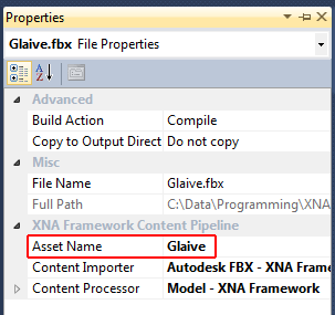
Content here is an object initialized by the Microsoft.Xna.Framework.Game, and is used to load and store most resources that your game will work with. If you're fuzzy on the odd <> syntax, you may wish to refresh a little on C# Generics. The string in this case refers to the model file itself! So if you're using something else, you'll want to change this. Something to note here, is that yes, there is no extension on that file name! This is because XNA's content system does some cool things. To visually see why, Right Click->Properties on your model in the content project. Note the Asset Name property.


And yes, you can change it.
By default, it's the name of the file minus extension. This is what Content.Load looks for specifically, so be careful if you change it. Please note! If you have two assets of different types with the same name, perhaps a texture and a model, you will get a name conflict! Changing the name of a texture just for that can be a bit of an irritation, so it's always nice plus to make sure that's covered during the modeling process.

The last part is a little bit more complicated, as it involves drawing the model. As simple as XNA might be, drawing 3D stuff is still a complicated task! But they've made it a darn sight simpler than it used to be, that's for sure. So! In the Draw method, right after the call to GraphicsDevice.Clear


Matrix[] transforms = new Matrix[glaiveModel.Bones.Count];
glaiveModel.CopyAbsoluteBoneTransformsTo(transforms);


foreach (ModelMesh mesh in glaiveModel.Meshes)
{
foreach (BasicEffect effect in mesh.Effects)
{
effect.EnableDefaultLighting();
effect.World      = transforms[mesh.ParentBone.Index] * Matrix.CreateRotationY((float)gameTime.TotalGameTime.TotalSeconds);
effect.View       = Matrix.CreateLookAt(new Vector3(3, 4, 3), Vector3.Zero, Vector3.Up);
effect.Projection = Matrix.CreatePerspectiveFieldOfView( MathHelper.ToRadians(45.0f), GraphicsDevice.Viewport.AspectRatio, 0.1f, 1000.0f);
}
mesh.Draw();
}


Wooh~


Matrix[] transforms = new Matrix[glaiveModel.Bones.Count];
glaiveModel.CopyAbsoluteBoneTransformsTo(transforms);


The first two lines are a little weird, and really, it took me forever to figure out exactly what was going on with it. The basic idea is that it's one last transformation that gets applied to your object from the modeling tool. Often it's just the 'object' transform, any rotation, translation, or scaling that you applied to your entire model back in Maya, or Blender or whatever. Also, 3D applications often use different internal representations of 3D space. Some of them will say the Y axis is up, some of them will say the Z axis is up... and all sorts of other strange variations on that idea. This last transform is a great place for them to correct into whatever is standard for the model format!


foreach (ModelMesh mesh in glaiveModel.Meshes)
{
foreach (BasicEffect effect in mesh.Effects)
{


After that, the two foreach loops just iterate through all the meshes and shaders/effects that are stored in the model. Yes, models will frequently contain multiple meshes in them! Most frequently, this is because they use different materials.


foreach (BasicEffect effect in mesh.Effects)
{
effect.EnableDefaultLighting();


The BasicEffect class is a default shader that XNA applies to all Models loaded in the regular fashion. It's just a nice, convenient tool to get you up and running really quick. Usually, this will get replaced by a custom shader/effect as your game gets more visually appealing. If you aren't sure what a shader is, it's basically a small bit of code that runs on the graphics card and describes exactly how 3D geometry gets transformed and lit/colored onto the screen, hence the light and position info.

effect.World      = transforms[mesh.ParentBone.Index] * Matrix.CreateRotationY((float)gameTime.TotalGameTime.TotalSeconds);


This bit here is the basic transformation information. As mentioned before, that first bit, transforms[mesh.ParentBone.Index] is just a reference to that last transform stored by the modeling tool, but the call to Matrix.CreateRotationY is actually going to give a rotation to the model around the Y axis based on time.


effect.View       = Matrix.CreateLookAt(new Vector3(3, 4, 3), Vector3.Zero, Vector3.Up);
effect.Projection = Matrix.CreatePerspectiveFieldOfView( MathHelper.ToRadians(45.0f), GraphicsDevice.Viewport.AspectRatio, 0.1f, 1000.0f);


These two lines deal with camera information. One of the issues with 3D space, is that you have to tell exactly where you're looking from. Frequently this can be kinda tricky, but fortunately, Matrix.CreateLookAt is a pretty easy solution for a really basic 3D scene. All you have to do is specify where the camera is, where it's looking at, and what direction is up! A little less intuitive is the projection, which describes how 3D information gets squished into 2D polygons that can then actually be drawn on your 2D monitor. The first argument is the field of view, which basically describes how much of the 360 degrees of space you can see at any given time. Computer math works with radians, rather than degrees, so we use a nice XNA utility to convert it for us. After that, it needs to make sure the polygons are stretched to match the width/height ratio, or aspect ratio of your monitor. The last two are the near and far clipping plane, or how close and how far can object be drawn without getting ignored.


mesh.Draw();


This one then, just takes all the settings provided, and draws to screen! Yay~!


I like to think it's a nice model too =D
You can find the entire project for download right here. If you aren't doing the phone thing, and it's giving you issues with that, the easiest way to fix it is to right click on Basic3DTutorial WP7 in the solution Explorer, and say 'Unload Project'

Sunday, December 11, 2011

SceneGraph Sample

So, scene graphs! I used to love the darned things, but now I have some mildly mixed feelings on them. Regardless, they're still pretty awesome, so I whipped up a quick bit of sample code! (Full source can be found at the bottom of the article)

But first, a quick description of what a scene graph is. It's basically a tree-like structure used to represent the data in your game's scene. The advantage of using a tree structure, is that you can use the parent/child relationship to inherit information, like position and orientation! This can make it extremely easy to do things like... stick arrows into people's knees! Or a helmet on top of your player's head, y'know, possibly even things like containers and inventories.


Just re-using an illustration I made last time I talked about scene graphs. It's still pertinent ;)

As it so happens, it's not all that hard to do this through code. So here's a quick 3D example of using a scene graph inside of XNA 4.0.

It's impossible to use a DrawableGameComponent for our scene graph nodes, primarily because the LoadContent method is declared as protected, but if you're familiar with XNA, then you'll notice that the SceneNode class very much resembles a DrawableGameComponent.


class SceneNode
    {
        #region Fields
        /// <summary>
        /// A list of child SceneNodes underneath this node.
        /// </summary>
        List<SceneNode> mChildren;
        #endregion

        #region Properties
        /// <summary>
        /// Our link back to the game that created us, allows us to add content and the like
        /// </summary>
        public Game        Game      { get; protected set; }
        /// <summary>
        /// The parent node in the SceneGraph heirarchy, if this is null, then it has to 
        /// be the top item in the tree.
        /// </summary>
        public SceneNode   Parent    { get; protected set; }
        /// <summary>
        /// A 3D location and orientation! Does cool things, check it =D
        /// </summary>
        public Transform3D Transform { get; set; }
        /// <summary>
        /// Sets whether or not this node is drawing. Defaults to true.
        /// </summary>
        public bool        Visible   { get; set; }
        /// <summary>
        /// This sets if the node will actually update and draw, it might be a productive 
        /// idea to attach an event of some sort to this property. Defaults to true.
        /// </summary>
        public bool        Enabled   { get; set; }
        /// <summary>
        /// This is the transform matrix that takes into consideration all of the parent
        /// node locations.
        /// </summary>
        public Matrix      TransformMatrix
        {
            get
            {
                if (Parent == null)
                    return Transform.Transform;
                else
                    return Transform.Transform * Parent.TransformMatrix;
            }
        }
        #endregion

        #region Constructor
        /// <summary>
        /// Basic constructor, copies and initializes values
        /// </summary>
        /// <param name="aGame">A link to the game that created us!</param>
        /// <param name="aParent">The parent node for this SceneNode, can be null to indicate a top level SceneNode</param>
        public SceneNode(Game aGame, SceneNode aParent)
        {
            Game      = aGame;
            Parent    = aParent;
            Visible   = true;
            Enabled   = true;
            mChildren = new List<SceneNode>();
            Transform = new Transform3D();

            // if there is a parent object, add this object to the parent's children
            if (Parent != null)
                Parent.mChildren.Add(this);
        }
        #endregion

        #region Virtual methods
        public virtual void Initialize ()
        {
            // initialize all child nodes
            for (int i = 0; i < mChildren.Count; i++)
                mChildren[i].Initialize();
        }
        public virtual void LoadContent()
        {
            // load content for all child nodes
            for (int i = 0; i < mChildren.Count; i++)
                mChildren[i].LoadContent();
        }

        public virtual void Update(float aTime)
        {
            // update andy child nodes that are actually enabled
            for (int i = 0; i < mChildren.Count; i++)
                if (mChildren[i].Enabled)
                    mChildren[i].Update(aTime);
        }
        public virtual void Draw  (float aTime)
        {
            // draw them if they're visible, and enabled
            for (int i = 0; i < mChildren.Count; i++)
                if (mChildren[i].Visible && mChildren[i].Enabled)
                    mChildren[i].Draw(aTime);
        }
        #endregion
    }

And that's reasonably straightforward, there's really nothing all that tricky in there. After that's out of the way, all you need to do is.. either inherit from it, or set up a component system! Inheritance is the easiest, so here's an example of a basic 3D object that uses the SceneNode.


class Basic3DObject : SceneNode
    {
        #region Fields
        string mModelName;
        Model  mModel;
        #endregion

        #region Constructor
        public Basic3DObject(Game aGame, SceneNode aParent, string aModelName)
            : base(aGame, aParent)
        {
            // store for loading later
            mModelName = aModelName;
        }
        #endregion

        #region Overrides
        public override void LoadContent()
        {
            // load the model we have stored!
            mModel = Game.Content.Load<Model>(mModelName);

            // need this still, that way any child objects can still get loaded
            base.LoadContent();
        }

        public override void Draw(float aTime)
        {
            // Copy any parent transforms.
            Matrix[] transforms = new Matrix[mModel.Bones.Count];
            mModel.CopyAbsoluteBoneTransformsTo(transforms);

            // Draw the model. A model can have multiple meshes, so loop.
            foreach (ModelMesh mesh in mModel.Meshes)
            {
                // This is where the mesh orientation is set, as well 
                // as our camera and projection.
                foreach (BasicEffect effect in mesh.Effects)
                {
                    effect.EnableDefaultLighting();
                    effect.World      = transforms[mesh.ParentBone.Index] * TransformMatrix;
                    effect.View       = Camera.ViewMatrix;
                    effect.Projection = Camera.ProjectionMatrix;
                }
                // Draw the mesh, using the effects set above.
                mesh.Draw();
            }

            base.Draw(aTime);
        }
        #endregion
    }

And again, you can see it behaves almost exactly the same as a regular DrawableGameComponent! So it's not all that different from what you've already been working with~ Lastly, putting it all together in an example:

Spinning spaceships! Not the most practical thing, but hey.


public class Game1 : Microsoft.Xna.Framework.Game
    {
        GraphicsDeviceManager graphics;
        SpriteBatch spriteBatch;

        // scene nodes, for easy access
        SceneNode mRoot;
        SceneNode mCenterShip;
        SceneNode mMiddleShip1;
        SceneNode mMiddleShip2;

        SceneNode mOuterShip1;
        SceneNode mOuterShip2;
        SceneNode mOuterShip3;
        SceneNode mOuterShip4;

        public Game1()
        {
            graphics = new GraphicsDeviceManager(this);
            Content.RootDirectory = "Content";
        }

        protected override void Initialize()
        {
            mRoot = new SceneNode(this, null);

            // set up a large ship in the center, everything will rotate around it
            mCenterShip = new Basic3DObject(this, mRoot, "Ship");

            // set up two orbiting ships, note that their parent is mCenterShip
            mMiddleShip1 = new Basic3DObject(this, mCenterShip, "Ship");
            mMiddleShip1.Transform.Position = new Vector3(500, 0, 0);
            mMiddleShip1.Transform.ScaleSc  = 0.5f;
            mMiddleShip2 = new Basic3DObject(this, mCenterShip, "Ship");
            mMiddleShip2.Transform.Position = new Vector3(-500, 0, 0);
            mMiddleShip2.Transform.ScaleSc  = 0.5f;

            // set up two orbiting ships per orbiting ship, note how the scale is the same,
            // but when running, they're still smaller.
            mOuterShip1 = new Basic3DObject(this, mMiddleShip1, "Ship");
            mOuterShip1.Transform.Position = new Vector3(500, 0, 0);
            mOuterShip1.Transform.ScaleSc  = 0.5f;
            mOuterShip2 = new Basic3DObject(this, mMiddleShip1, "Ship");
            mOuterShip2.Transform.Position = new Vector3(-500, 0, 0);
            mOuterShip2.Transform.ScaleSc  = 0.5f;
            mOuterShip3 = new Basic3DObject(this, mMiddleShip2, "Ship");
            mOuterShip3.Transform.Position = new Vector3(500, 0, 0);
            mOuterShip3.Transform.ScaleSc  = 0.5f;
            mOuterShip4 = new Basic3DObject(this, mMiddleShip2, "Ship");
            mOuterShip4.Transform.Position = new Vector3(-500, 0, 0);
            mOuterShip4.Transform.ScaleSc  = 0.5f;

            // do a really simple, easy camera setup
            Camera.ProjectionMatrix = Matrix.CreatePerspectiveFieldOfView(MathHelper.PiOver2, 800f / 480f, 0.1f, 2000f);
            Camera.ViewMatrix       = Matrix.CreateLookAt(new Vector3(500, 500, 500), Vector3.Zero, Vector3.Up);

            base.Initialize();
        }

        protected override void LoadContent()
        {
            // Create a new SpriteBatch, which can be used to draw textures.
            spriteBatch = new SpriteBatch(GraphicsDevice);

            // only need the one call, everything gets passed down, since it's a SceneGraph =D
            mRoot.LoadContent();
        }

        protected override void Update(GameTime gameTime)
        {
            // Allows the game to exit
            if (Keyboard.GetState().IsKeyDown(Keys.Escape))
                this.Exit();

            // rotate the very middle ship, which should rotate all the ships, based on the SceneGraph architecture
            if (Keyboard.GetState().IsKeyDown(Keys.Q))
            {
                mCenterShip.Transform.Rotation += new Vector3(0, 0.05f, 0);
            }
            // rotate the middle ships
            if (Keyboard.GetState().IsKeyDown(Keys.W))
            {
                mMiddleShip1.Transform.Rotation += new Vector3(0, 0.05f, 0);
                mMiddleShip2.Transform.Rotation += new Vector3(0, 0.05f, 0);
            }
            // and lastly
            if (Keyboard.GetState().IsKeyDown(Keys.E))
            {
                mOuterShip1.Transform.Rotation += new Vector3(0, 0.05f, 0);
                mOuterShip2.Transform.Rotation += new Vector3(0, 0.05f, 0);
                mOuterShip3.Transform.Rotation += new Vector3(0, 0.05f, 0);
                mOuterShip4.Transform.Rotation += new Vector3(0, 0.05f, 0);
            }

            // only need the one call, everything gets passed down, since it's a SceneGraph =D
            mRoot.Update((float)gameTime.ElapsedGameTime.TotalSeconds);

            base.Update(gameTime);
        }

        protected override void Draw(GameTime gameTime)
        {
            GraphicsDevice.Clear(Color.CornflowerBlue);

            // only need the one call, everything gets passed down, since it's a SceneGraph =D
            mRoot.Draw((float)gameTime.ElapsedGameTime.TotalSeconds);

            base.Draw(gameTime);
        }
    }

So hopefully that's at least a little bit informative =D The full source code includes a few extra things not shown above, so check it out!

Source code can be downloaded here

Monday, March 14, 2011

Unity Videos

I just made a video introducing some of the basic elements of Unity. I'm kinda excited, I don't do video stuff all that often =D Two parts on Youtube!

Part One


Part Two